Camera Usage
1. Camera Introduction
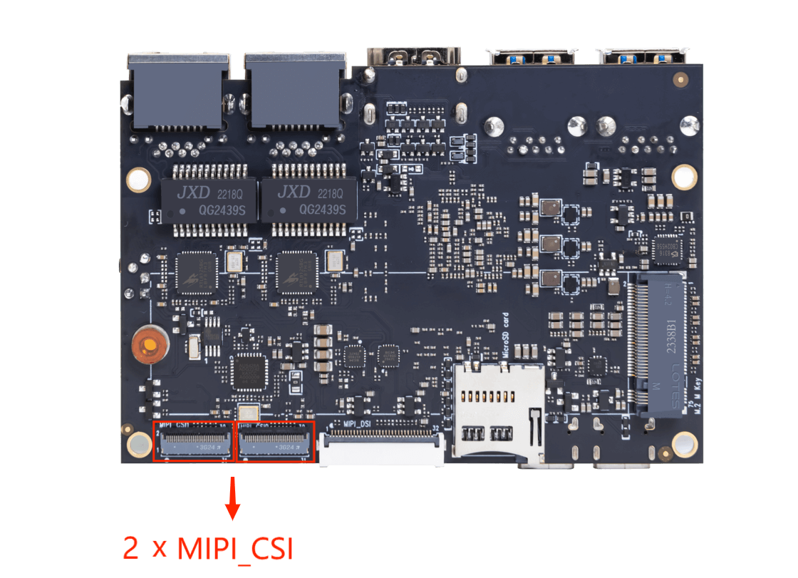
The ArmSoM series products use cameras with the MIPI-CSI interface
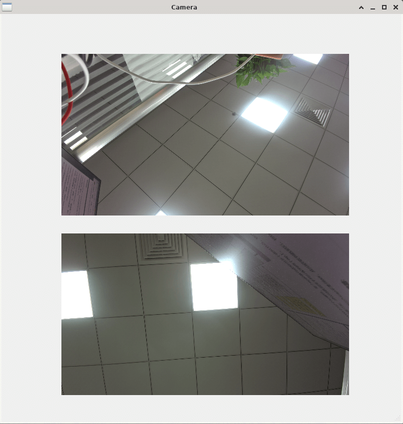
The ArmSoM-Sige7 supports dual-camera display:
2. RK3588 Hardware Path Block Diagram
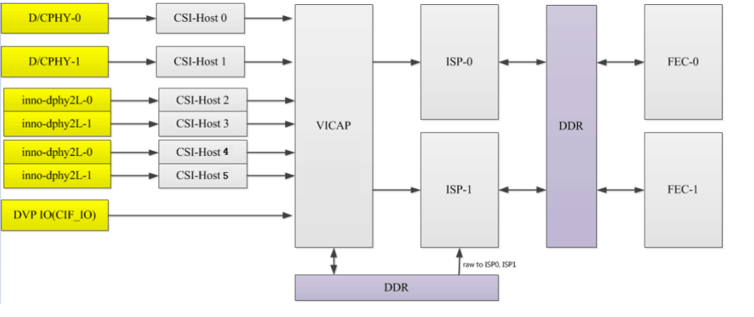
The RK3588 supports 2 ISP hardware modules, and each ISP device can virtualize multiple virtual nodes. The software reads the image data from DDR for each path in turn and processes it through the ISP. For multi-camera solutions, it is recommended to evenly distribute the data flow to the two ISPs.
Readback: refers to the data being collected into DDR after going through VICAP, and after the application obtains the data, the buffer address is pushed to the ISP, and then the ISP obtains the image data from DDR.
3. RK3588 Camera Path:
Multi-sensor Support:
- A single hardware ISP supports up to 4 multiplexed paths, and the supported resolutions for ISP multiplexing are as follows:
- 2 paths multiplexed: maximum resolution 3840x2160, DTS corresponding configuration 2 rkisp_vir devices.
- 3 or 4 paths multiplexed: maximum resolution 2560x1536, DTS corresponding configuration 3 or 4 rkisp_vir devices.
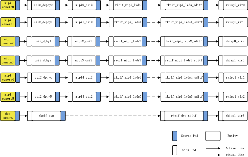
- The hardware supports collecting up to 7 sensor paths: 6 MIPI + 1 DVP, and the software path for multiple sensors is as follows:
The following diagram shows the RK3588 camera connection link, which can support up to 7 cameras.
4. Link Analysis:

In the figure: mipi camera2---> csi2_dphy1 ---> mipi2_csi2 ---> rkcif_mipi_lvds2--->rkcif_mipi_lvds2_sditf --->rkisp0_vir2
Corresponding node: imx415 ---> csi2_dphy0 ---> mipi2_csi2 ---> rkcif_mipi_lvds2--->rkcif_mipi_lvds2_sditf --->rkisp0_vir2
Link relationship: sensor---> csi2 dphy---->mipi csi host--->vicap
Solid link analysis: Camera sensor ---> dphy ---> mipi_csi2 module parses mipi protocol ---> vicap ( rkcif node represents vicap )
Dashed link analysis: vicap ---> rkcif_mipi_lvds2_sditf ---> isp
The link relationship between each vicap node and the ISP is indicated by the XXX_sditf node that is virtually created to correspond to that relationship.
5. ArmSoM-Sige7 Dual-Camera Debugging
Here, we use the imx415 camera as an example to analyze the ArmSoM-Sige7 dual-camera debugging.
5.1 Schematic Diagram
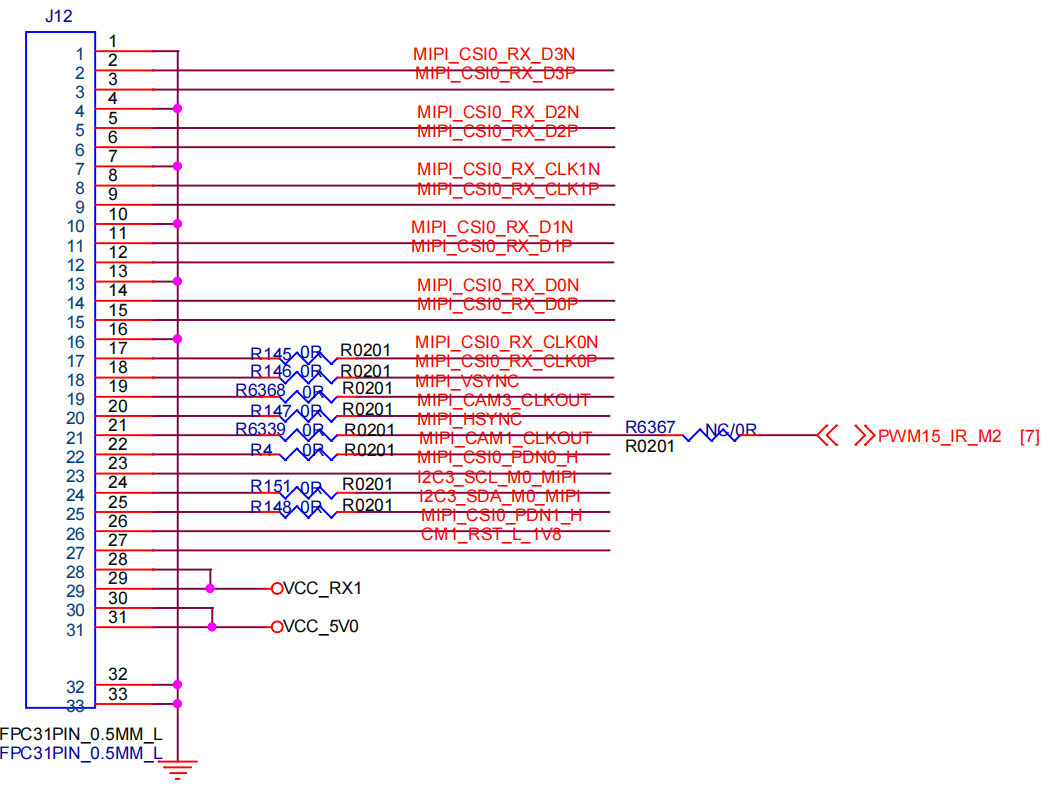
Camera1: CSI0_MIPI:
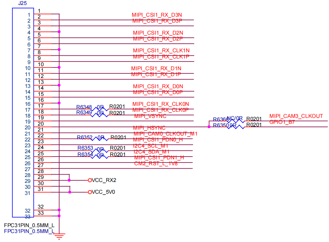
Camera2: CS1_MIPI:
5.2 DTS Configuration for Dual Cameras:
- Link Configuration 1: imx415 —> csi2_dphy0 —> mipi2_csi2 —> rkcif_mipi_lvds2—>rkcif_mipi_lvds2_sditf —>rkisp0_vir2
- Link Configuration 2: imx415 —> csi2_dphy3 —> mipi4_csi2 —> rkcif_mipi_lvds4—>rkcif_mipi_lvds4_sditf —>rkisp1_vir1
&i2c3 {
    status = "okay";

    imx415: imx415@1a {
        status = "okay";
        compatible = "sony,imx415";
        reg = <0x1a>;
        clocks = <&cru CLK_MIPI_CAMARAOUT_M3>;
        clock-names = "xvclk";
        pinctrl-names = "default";
        pinctrl-0 = <&mipim0_camera3_clk>;
        power-domains = <&power RK3588_PD_VI>;
        pwdn-gpios = <&gpio1 RK_PB0 GPIO_ACTIVE_HIGH>;
        reset-gpios = <&gpio4 RK_PA0 GPIO_ACTIVE_LOW>;
        rockchip,camera-module-index = <0>;
        rockchip,camera-module-facing = "back";
        rockchip,camera-module-name = "CMK-OT2022-PX1";
        rockchip,camera-module-lens-name = "IR0147-50IRC-8M-F20";
        port {
            imx415_out0: endpoint {
                remote-endpoint = <&mipidphy0_in_ucam0>;
                data-lanes = <1 2 3 4>;
            };
        };
    };
};

&i2c4 {
    status = "okay";
    pinctrl-names = "default";
    pinctrl-0 = <&i2c4m1_xfer>;
    imx415_1: imx415_1@1a {
        status = "okay";
        compatible = "sony,imx415";
        reg = <0x1a>;
        clocks = <&cru CLK_MIPI_CAMARAOUT_M2>;
        clock-names = "xvclk";
        pinctrl-names = "default";
        pinctrl-0 = <&mipim0_camera2_clk>;
        power-domains = <&power RK3588_PD_VI>;
        pwdn-gpios = <&gpio3 RK_PA2 GPIO_ACTIVE_HIGH>;
        reset-gpios = <&gpio3 RK_PA0 GPIO_ACTIVE_LOW>;
        rockchip,camera-module-index = <1>;
        rockchip,camera-module-facing = "back";
        rockchip,camera-module-name = "CMK-OT2022-PX1";
        rockchip,camera-module-lens-name = "IR0147-50IRC-8M-F20";
        port {
            imx415_out3: endpoint {
                remote-endpoint = <&mipidphy3_in_ucam3>;
                data-lanes = <1 2 3 4>;
            };
        };
    };

};

&csi2_dphy0_hw {
    status = "okay";
};

&csi2_dphy1_hw {
    status = "okay";
};

&csi2_dphy0 {
    status = "okay";

    ports {
        #address-cells = <1>;
        #size-cells = <0>;

        port@0 {
            reg = <0>;
            #address-cells = <1>;
            #size-cells = <0>;

            mipidphy0_in_ucam0: endpoint@1 {
                reg = <1>;
                remote-endpoint = <&imx415_out0>;
                data-lanes = <1 2 3 4>;
            };

        };

        port@1 {
            reg = <1>;
            #address-cells = <1>;
            #size-cells = <0>;

            csidphy0_out: endpoint@0 {
                reg = <0>;
                remote-endpoint = <&mipi2_csi2_input>;
            };
        };
    };
};

&csi2_dphy3 {
    status = "okay";

    ports {
        #address-cells = <1>;
        #size-cells = <0>;

        port@0 {
            reg = <0>;
            #address-cells = <1>;
            #size-cells = <0>;

            mipidphy3_in_ucam3: endpoint@1 {
                reg = <1>;
                remote-endpoint = <&imx415_out3>;
                data-lanes = <1 2 3 4>;
            };

        };

        port@1 {
            reg = <1>;
            #address-cells = <1>;
            #size-cells = <0>;

            csidphy3_out: endpoint@0 {
                reg = <0>;
                remote-endpoint = <&mipi4_csi2_input>;
            };
        };
    };
};

&mipi2_csi2 {
    status = "okay";

    ports {
        #address-cells = <1>;
        #size-cells = <0>;

        port@0 {
            reg = <0>;
            #address-cells = <1>;
            #size-cells = <0>;

            mipi2_csi2_input: endpoint@1 {
                reg = <1>;
                remote-endpoint = <&csidphy0_out>;
            };
        };

        port@1 {
            reg = <1>;
            #address-cells = <1>;
            #size-cells = <0>;

            mipi2_csi2_output: endpoint@0 {
                reg = <0>;
                remote-endpoint = <&cif_mipi2_in0>;
            };
        };
    };
};

&mipi4_csi2 {
    status = "okay";

    ports {
        #address-cells = <1>;
        #size-cells = <0>;

        port@0 {
            reg = <0>;
            #address-cells = <1>;
            #size-cells = <0>;

            mipi4_csi2_input: endpoint@1 {
                reg = <1>;
                remote-endpoint = <&csidphy3_out>;
            };
        };

        port@1 {
            reg = <1>;
            #address-cells = <1>;
            #size-cells = <0>;

            mipi4_csi2_output: endpoint@0 {
                reg = <0>;
                remote-endpoint = <&cif_mipi_in4>;
            };
        };
    };
};

&rkcif {
    status = "okay";
};

&rkcif_mipi_lvds2 {
    status = "okay";

    port {
        cif_mipi2_in0: endpoint {
            remote-endpoint = <&mipi2_csi2_output>;
        };
    };
};

&rkcif_mipi_lvds2_sditf {
    status = "okay";

    port {
        mipi_lvds2_sditf: endpoint {
            remote-endpoint = <&isp0_vir2>;
        };
    };
};

&rkcif_mipi_lvds4 {
    status = "okay";

    port {
        cif_mipi_in4: endpoint {
            remote-endpoint = <&mipi4_csi2_output>;
        };
    };
};

&rkcif_mipi_lvds4_sditf {
    status = "okay";

    port {
        mipi4_lvds_sditf: endpoint {
            remote-endpoint = <&isp1_vir1>;
        };
    };
};

&rkcif_mmu {
    status = "okay";
};

&rkisp0 {
    status = "okay";
};

&isp0_mmu {
    status = "okay";
};

&rkisp0_vir2 {
    status = "okay";

    port {
        #address-cells = <1>;
        #size-cells = <0>;

        isp0_vir2: endpoint@0 {
            reg = <0>;
            remote-endpoint = <&mipi_lvds2_sditf>;
        };
    };
};

&rkisp1 {
    status = "okay";
};

&isp1_mmu {
    status = "okay";
};

&rkisp1_vir1 {
    status = "okay";

    port {
        #address-cells = <1>;
        #size-cells = <0>;

        isp1_vir1: endpoint@0 {
            reg = <0>;
            remote-endpoint = <&mipi4_lvds_sditf>;
        };
    };
};


&pinctrl {
    camera {
        cam_pwdn_gpio: cam-pwdn-gpio {
            rockchip,pins = <1 RK_PB0 RK_FUNC_GPIO &pcfg_pull_up>;
        };
    };
};
6. Debugging Tips
6.1 Check if the Camera is mounted under the i2c bus
i2cdetect -y 3
6.2 View the topology structure
media-ctl -d /dev/media0 -p
6.3 imx415 related log information
dmesg | grep imx415
6.4 View file information in the sys file system
The kernel will allocate device information description files for the camera under the directory /sys/class/video4linux
armsom@armsom:~$  grep imx415 /sys/class/video4linux/v*/name
/sys/class/video4linux/v4l-subdev2/name:m00_b_imx415 3-001a
/sys/class/video4linux/v4l-subdev7/name:m01_b_imx415 4-001a
Find the corresponding video node for the Camera:
armsom@armsom:~$ grep "" /sys/class/video4linux/v*/name | grep mainpath
/sys/class/video4linux/video22/name:rkisp_mainpath
/sys/class/video4linux/video31/name:rkisp_mainpath
We can see that in the ArmSoM-Sige7, the nodes corresponding to the dual cameras are: video22 and video31
6.5 Find all camera devices
armsom@armsom:~$ v4l2-ctl --list-devices
rkisp-statistics (platform: rkisp):
        /dev/video29
        /dev/video30
        /dev/video38
        /dev/video39

rkcif-mipi-lvds2 (platform:rkcif):
        /dev/media0
        /dev/media1

rkcif (platform:rkcif-mipi-lvds2):
        /dev/video0
        /dev/video1
        /dev/video2
        /dev/video3
        /dev/video4
        /dev/video5
        /dev/video6
        /dev/video7
        /dev/video8
        /dev/video9
        /dev/video10

rkcif (platform:rkcif-mipi-lvds4):
        /dev/video11
        /dev/video12
        /dev/video13
        /dev/video14
        /dev/video15
        /dev/video16
        /dev/video17
        /dev/video18
        /dev/video19
        /dev/video20
        /dev/video21

rkisp_mainpath (platform:rkisp0-vir0):
        /dev/video22
        /dev/video23
        /dev/video24
        /dev/video25
        /dev/video26
        /dev/video27
        /dev/video28
        /dev/media2

rkisp_mainpath (platform:rkisp1-vir1):
        /dev/video31
        /dev/video32
        /dev/video33
        /dev/video34
        /dev/video35
        /dev/video36
        /dev/video37
        /dev/media3
Among them, /dev/video22 and /dev/video31 are both camera devices.
6.6 View the preview formats supported by the device
The following is the query result of the video22 node: the imx415 camera:
armsom@armsom:~$ v4l2-ctl -d /dev/video22 --list-formats-ext
ioctl: VIDIOC_ENUM_FMT
        Type: Video Capture Multiplanar

        [0]: 'UYVY' (UYVY 4:2:2)
                Size: Stepwise 32x32 - 3840x2160 with step 8/8
        [1]: 'NV16' (Y/CbCr 4:2:2)
                Size: Stepwise 32x32 - 3840x2160 with step 8/8
        [2]: 'NV61' (Y/CrCb 4:2:2)
                Size: Stepwise 32x32 - 3840x2160 with step 8/8
        [3]: 'NV21' (Y/CrCb 4:2:0)
                Size: Stepwise 32x32 - 3840x2160 with step 8/8
        [4]: 'NV12' (Y/CbCr 4:2:0)
                Size: Stepwise 32x32 - 3840x2160 with step 8/8
        [5]: 'NM21' (Y/CrCb 4:2:0 (N-C))
                Size: Stepwise 32x32 - 3840x2160 with step 8/8
        [6]: 'NM12' (Y/CbCr 4:2:0 (N-C))
                Size: Stepwise 32x32 - 3840x2160 with step 8/8
6.7 View all information about the device:
armsom@armsom:~$ v4l2-ctl --all --device /dev/video22
Driver Info:
        Driver name      : rkisp_v6
        Card type        : rkisp_mainpath
        Bus info         : platform:rkisp0-vir0
        Driver version   : 2.3.0
        Capabilities     : 0x84201000
                Video Capture Multiplanar
                Streaming
                Extended Pix Format
                Device Capabilities
        Device Caps      : 0x04201000
                Video Capture Multiplanar
                Streaming
                Extended Pix Format
Media Driver Info:
        Driver name      : rkisp0-vir0
        Model            : rkisp0
        Serial           :
        Bus info         :
        Media version    : 5.10.160
        Hardware revision: 0x00000000 (0)
        Driver version   : 5.10.160
Interface Info:
        ID               : 0x03000007
        Type             : V4L Video
Entity Info:
        ID               : 0x00000006 (6)
        Name             : rkisp_mainpath
        Function         : V4L2 I/O
        Pad 0x01000009   : 0: Sink
          Link 0x0200000a: from remote pad 0x1000004 of entity 'rkisp-isp-subdev' (Unknown V4L2 Sub-Device): Data, Enabled
Priority: 2
Format Video Capture Multiplanar:
        Width/Height      : 3840/2160
        Pixel Format      : 'NM12' (Y/CbCr 4:2:0 (N-C))
        Field             : None
        Number of planes  : 2
        Flags             :
        Colorspace        : sRGB
        Transfer Function : Rec. 709
        YCbCr/HSV Encoding: Rec. 709
        Quantization      : Full Range
        Plane 0           :
           Bytes per Line : 3840
           Size Image     : 8294400
        Plane 1           :
           Bytes per Line : 3840
           Size Image     : 4147200
Selection Video Capture: crop, Left 0, Top 0, Width 3840, Height 2160, Flags:
Selection Video Capture: crop_bounds, Left 0, Top 0, Width 3840, Height 2160, Flags:
Selection Video Output: crop, Left 0, Top 0, Width 3840, Height 2160, Flags:
Selection Video Output: crop_bounds, Left 0, Top 0, Width 3840, Height 2160, Flags:

Image Processing Controls

                     pixel_rate 0x009f0902 (int64)  : min=0 max=1000000000 step=1 default=1000000000 value=356800000 flags=read-only, volatile
6.8 Camera Preview
In the ArmSoM-Sige7, the preview commands for dual cameras are:
- Preview camera 1:
gst-launch-1.0 v4l2src device=/dev/video22 ! video/x-raw,format=NV12,width=3840,height=2160,framerate=30/1 ! videoconvert ! autovideosink
- Preview camera 2:
gst-launch-1.0 v4l2src device=/dev/video31 ! video/x-raw,format=NV12,width=3840,height=2160,framerate=30/1 ! videoconvert ! autovideosink
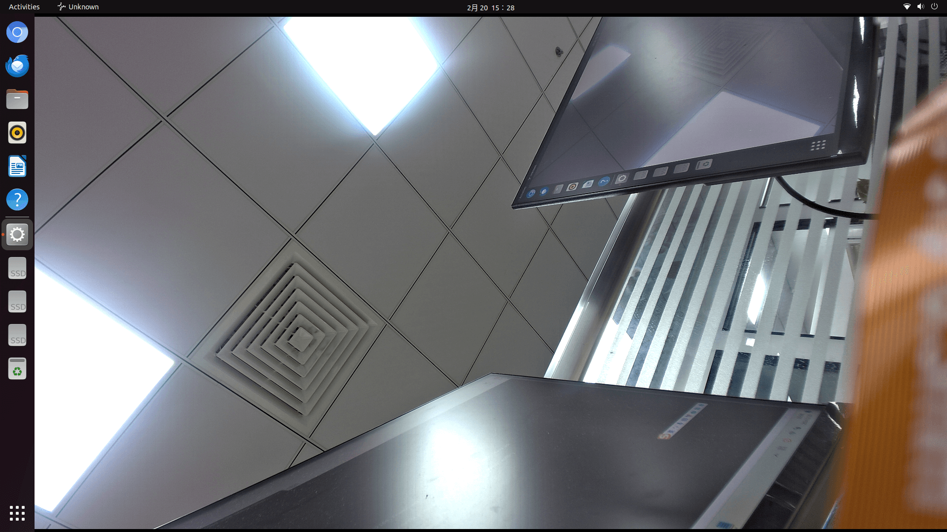
7. Camera Application Development
Customers can develop camera-related applications according to their own needs. The following is a dual-camera display application developed using QT: